Shipping and Order Information
- TRW Supply can usually ship in stock items same day before 3:30 PM
EST for no extra cost and before 5 PM with a rush fee
- Shipping options vary by location. Call for an accurate quote.
Warranty
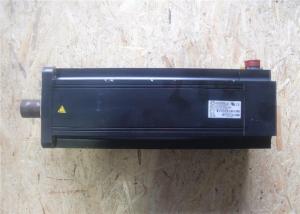
- The MHMJ022G1U comes with a 1 year warranty.
•Select a single and 3-phase common specifications corresponding to
the power supplies.
•Listed circuit breaker and magnetic contactor are manufactured by
Panasonic Electric Works.
To conform to EC Directives, install a circuit breaker which
conforms to IEC and UL Standards (Listed, marked) between noise
filter and power supply without fail.
•For details of noise filter, refer to Page A4-138.
<Remarks>
•Select a circuit breaker and noise filter which match to the
capacity of power supply (including a load condition).
•Terminal block and earth terminals
•Use a copper conductor cables with temperature rating of 60˚C or
higher.
•Earth terminals for Frame A to D are M4 and M5 for Frame E, F.
• Larger tightening toque for screws than the max.value (M4 : 1.2
N·m, M5 : 2.0 N·m) may damage the terminal block.
• Mounting screws on the cover of terminal block for frames E, F
should be tightened with 0.2 N·m torque.
Application of torque larger than 0.2 N·m may damage the thread on
the driver.
•Use an earth cable with the same diameter as that of the main
circuit cable.
If the diameter of the main circuit cable is 1.6mm2 or less, use an
earth cable with a diameter of 1.6mm2 (AWG14).
•Use the attached exclusive connector for A to D-frame, and
maintain the peeled off length of 8 tot 9mm.
•Tighten the screws of the connector, CN X5 for the host controller
with the torque of 0.3 to 0.35 N·m.
•Larger torque than 0.35N·m may damage the connector at the driver
side.

A point number increments by 1 automatically whenever an operation
command is given.
A step operation can be performed easily only by turning the STB
signal on/off.
You can operate the motor actually using this console, set a target
position and execute some test operations.
Load inertia is determined at real time in the state of actual
operation and gain corresponding to the rigidity is set
automatically.
Load inertia is determined by driving the equipment with operation
comman
. Regenerative brake frequency represents the frequency of the
motor's stops from the rated speed with deceleration without load.
. If the load is connected, frequency will be defines as 1/(m+1),
where m=load moment of inertia/rotor moment of inertia.
. When the motor speed exceeds the rated speed, regenerative brake
frequency is in inverse proportion to the
square of (running speed/rated speed).
. Power supply voltage is AC115V (at 100V of the main voltage).
If the supply voltage fluctuates, frequency is in inverse
proportion to the square of (Running supply voltage/115)
relative to the value in the table.
. When regeneration occurs continuously such cases as running speed
frequently changes or vertical feeding, consult us or
a dealer.
2. If the effective torque is within the rated torque, there is no
limit in generative brake.
3. Consult us or a dealer if the load moment of inertia exceeds the
specified value.
4. Specified releasing time is obtained with the use of surge
absorber for brake (Z15D271 by Ishizuka Electronic or equivalent).
( ) represents the actually measured value using a diode (200V, 1A
or equivalent)


